

Concurs : Line Follower
Acest articol este publicat in cadrul concursului Robofun 2012. Perioada de votare pentru acest proiect s-a incheiat. Acest proiect a acumulat un numar de 23 de voturi.
This is my second Line Follower Robot and as its name suggest, it is a robot whose purpose is following a line. This robot can be used in contests where a robot must follow a route delimited by a black line on a white background in the shortest time possible.
This robot is really simple to make and then you can use this platform for other purposes.
The MOTORS:
The motors I used for this robot are 2 servomotors modified for speed. You can also use other motor if it’ s good enough… I didn’t have any so I modded 2 servomotors.
HOW TO MOD THE SERVOMOTORS (look at the pictures)
1. Remove the four screws from the servo and take it all apart.
2. Remove the electronics keeping only the wires from the motor (I kept the other 3 wires from the potentiometer but you don’t have to).
3. Try to fit the gears except for one. I glued the big gear to the one beneath it so as to be high enogh to „get out” of the case. It isn’t exactly a rule for how to do this… various servos will have various gears so you will need to try until you will find the best „combination”.
4. Put everything toghether.
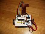
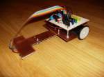
The BODY (look at the picture):
The base of the robot is made of PCB cutted to the properly size.
You will also need 5 screws:
– 2 for putting together the front and the base of the robot
– one for lifting the sensors off the ground (you can use something else here, if you have)
– 2 for lifting and fixing the microcontroller PCB
The SENSORS:
I made my sensors using 5 SMD IR emiting diodes, 5 SMD phototransistors and 5 1k SMD resistors. Between the phototransistor and the IR I put some black silicone so the IR light would not come directly to the phototransistor. The PCB design is in the archive „line follower.rar”. It is made in PROTEUS, but I have a word document including all the PCB designs which can be printed on glossy paper or Press and Peel, and then transfered to the PCB using the method of the iron.


Acest articol este publicat in cadrul concursului Robofun 2012. Perioada de votare pentru acest proiect s-a incheiat. Acest proiect a acumulat un numar de 23 de voturi.
Curs Gratuit Arduino

Comandă piese de robotică & electronică originale

