

gsm & 3G shield breadboard tutorial
Pin to pin compatible, compact and light weight modules and having embedded USB ports, c-uGSM and d-u3G shields (micro) are itbrainpower.net latest GSM / 3G-UMTS shields compatible with Arduino, Raspeberry PI, Raspberry PI2 or with any other 2.8-5V micro-controller board. gSPS adapter it is a „plug and run” SWITCHING POWER SUPPLY companion for c-uGSM and d-u3G shields.
Next, I will show to you how to speed up your GSM / 3G projects prototyping.
What you will need
- c-uGSM shield (micro) v1.13 1 pcs. or,
- d-u3G shield (micro) v1.13 1 pcs.
- g-SPS adapter 4V [DDRV] v1.02 1pcs.
- breadboard 1pcs.
- some standard 2.54 mm pinheaders
- ..and SIM card, antenna… I will not talk about those.
c-uGSM, d-u3G shields and gSPS hardware references
All examples bellow are demonstrated based on c-uGSM and gSPS 4V [DDRV] (used for direct 3G-GSM shield powering in „NO Lithium Polymer” powering schema).
NO breadboard differences for gSPS 5V [LiPOL] usage (used in „WITH Lithium Polymer” powering), but you will need to connect one Lithium Polymer battery to the CSM or 3G shield.
d-u3G differences – will be revealed later.
3G/GSM shields reference can be seen here. gSPS switching power supply reference may be found here.
GSM 3G shield breadboard prototyping
Solder the strait row headers to the boards. Solder the barrel connector to the gSPS power supply, if needed.

Hint: 2×10 pin headers can be used for all examples provided and for 99.99% of your projects. In this case, in picture up here, start from right for c-uGSM / left for g-SPS (RX) to the left for c-uGSM / right for g-SPS and stop at the 10’th pin (STS).
Insert the power supply and the GSM shield in the breadboard as bellow pictures. SIM must be installed to the GSM shield, first. 😉
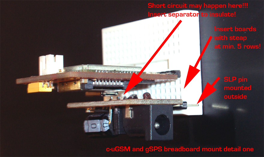

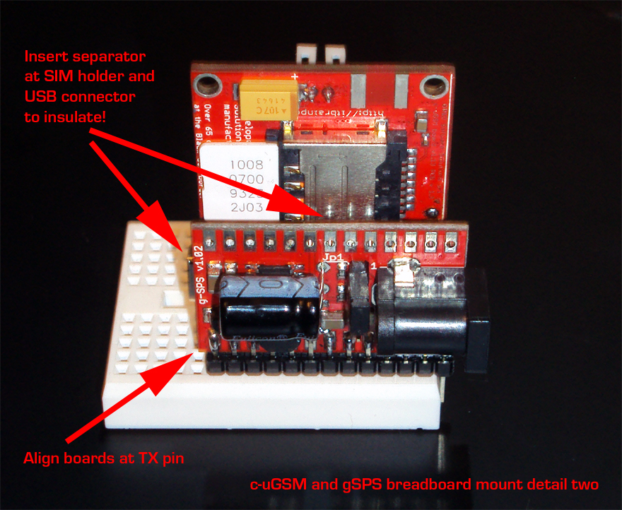
Between boards, a gap of minimum 5 rows it is required. Insulation separator (foam, cardboard,..) must be inserted between boards in order to prevent the SHORT CIRCUITS!
WARNING:
BOARDS MAY BEND WHEN INSERTED AND CAN CAUSE A SHORT CIRCUITS!!! TAKE ALL NECESSARY STEPS TO PREVENT THIS HAPPEN! YOU ARE THE ONLY RESPONSIBLE FOR HARDWARE HANDLING, USAGE AND WIRING!!!
3G shield (d-u3G shield) difference: at insertion moment, ALIGN both sides (TX 2 TX and SLP 2 SLP).
READY! Now you may continue to wire your project connecting other boards, starting from the breadboard contacts.
Credits
published by Dragos Iosub & itbrainpower.net team on http://itbrainpower.net/ projects and how to section
Curs Gratuit Arduino

Comandă piese de robotică & electronică originale

